- Home
- Opto-Electronics
This optical transceiver is designed for 10Gb/s serial optical interfaces for data communications through 9/125 micron single mode fiber (SMF). It supports 1.25Gb/s to 11.1Gb/s up to 10km distance.
Features:
- Hot pluggable
- 10Gb/s optical interface
- Up to 10km reach over SMF
- Compliant with SFP+ MSA
- SFP MSA package with duplex LC connector
- Digital Diagnostic Monitor Interface
- High transmission margin
- Single +3.3V power supply
- Very low EMI and excellent ESD protection
- Below 1.5W power consumption
- Wide data-rate range
- RoHS Compliant
Applications:
- 10G Ethernet
- Other high speed optical data communication links
Compliance:
- SFP+ MSA Compliant
- SFF-8472 reversion 9.5
- IEEE802.3-2005
- Telcordia GR-468-CORE
- FCC 47 CFR Part 15,Class B
- FDA 21 CFR 1040.10 and 1040.11,class1
- RoHS compliant
Ordering Information:
SFP-10G-L13
Specifications:
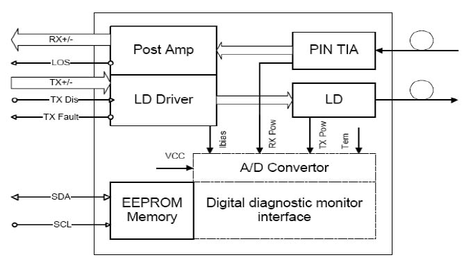
Functional Diagram

Absolute Maximum Ratings

Note: excess of the maximum absolute ratings can cause permanent damage to the module.General Operating Conditions

Electrical Input/Output Characteristics
Tx

Rx

Note 1: TD+/- are internally AC coupled with 100Ohm differential termination inside the module.
Note 2: Tx Fault and Rx LOS are open collector outputs, which should be pulled up with 4.7k to 10kOhm resistors on the host board. Pull up voltage between 2.0V and Vcc+0.3V
Note 3: RD+/- outputs are internally AC coupled, and should be terminated with 100Ohm (differential) at the user SERDES.Optical Characteristics
Transmitter (0~70?C@10.3125Gbps)

Receiver (0~70?C@10.3125Gbps)

Note 1. Measured at 10.3125b/s with PRBS 2^31 ? 1 NRZ test pattern.
Note 2. 20%~80%
Note 3. Under the ER worst case, measured at 10.3125 Gb/s with PRBS 2^31 ? 1 NRZ test pattern for BER < 1x10^-12SFP Module Control and Management
The SFP modules implement the 2-wire serial communication protocol as defined in the SFP MSA. The serial ID information of the SFP modules and Digital Diagnostic Monitor parameters can be accessed through the I2C interface at address A0h and A2h. The memory is mapped in following table. The DDM specification(A2h) is described in following tables. For more details of the memory map and byte definitions, please refer to the SFF-8472 (Rev 9.3, Aug. 2002), ?Digital Diagnostic Monitoring Interface for Optical Transceivers?. The DDM parameters have been internally calibrated.
Digital Diagnostic Memory Map

DDM Specification

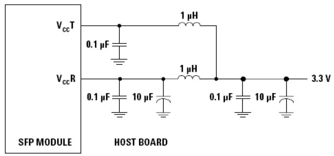
Recommended Power Supply Filter

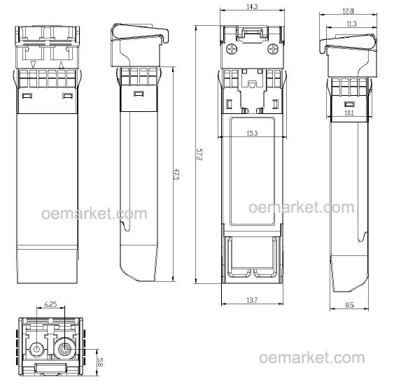
Note: Inductors with DC resistance of less than 1Ω should be used in order to maintain the required voltage at the SFP input pin at 3.3V. When the recommended supply filtering circuit is used, hot plugging of the SFP transceiver module will result in an inrush current of no more than 30 mA greater than the steady state value.Package Outline (mm)

10Gbps optical transceiver 1310nm, hot pluggable SFP, 10km reach over single mode fiberOur Offers
Contact Us
- Bitline System Pty. Ltd. 10 Fishburns Road, Galston, NSW 2159, Australia
- +61 2 98991412
- info@oemarket.com
oeMarket.com © 2024
